My first PCB
Assembling and Soldering
Table of Contents
Introduction
In the first part of my series I had finished the board in KiCad. What's missing now is the assembly, but for that I couldn't start right away.
First of all I had to wait for the boards to be shipped from OSH-Park. And secondly I still had to source all of the components: All of the passive elements, the LEDs and the buttons where no problem to find. The only problem was the MCU, the ATtiny85-10SU.
Due to the global chip shortage there were long lead times for many chips and even the ATtiny were affected. Thus I had to wait for some weeks, at least it took less time than stated for the chip to arrive.
Assembling the Board
I haven't yet mastered the art of soldering, but for this board it was enough. Thanks to the solder bridges to the MCU pins (which I had to fill anyways) I was able to quickly test the Charlieplexing of the LEDs. It worked.
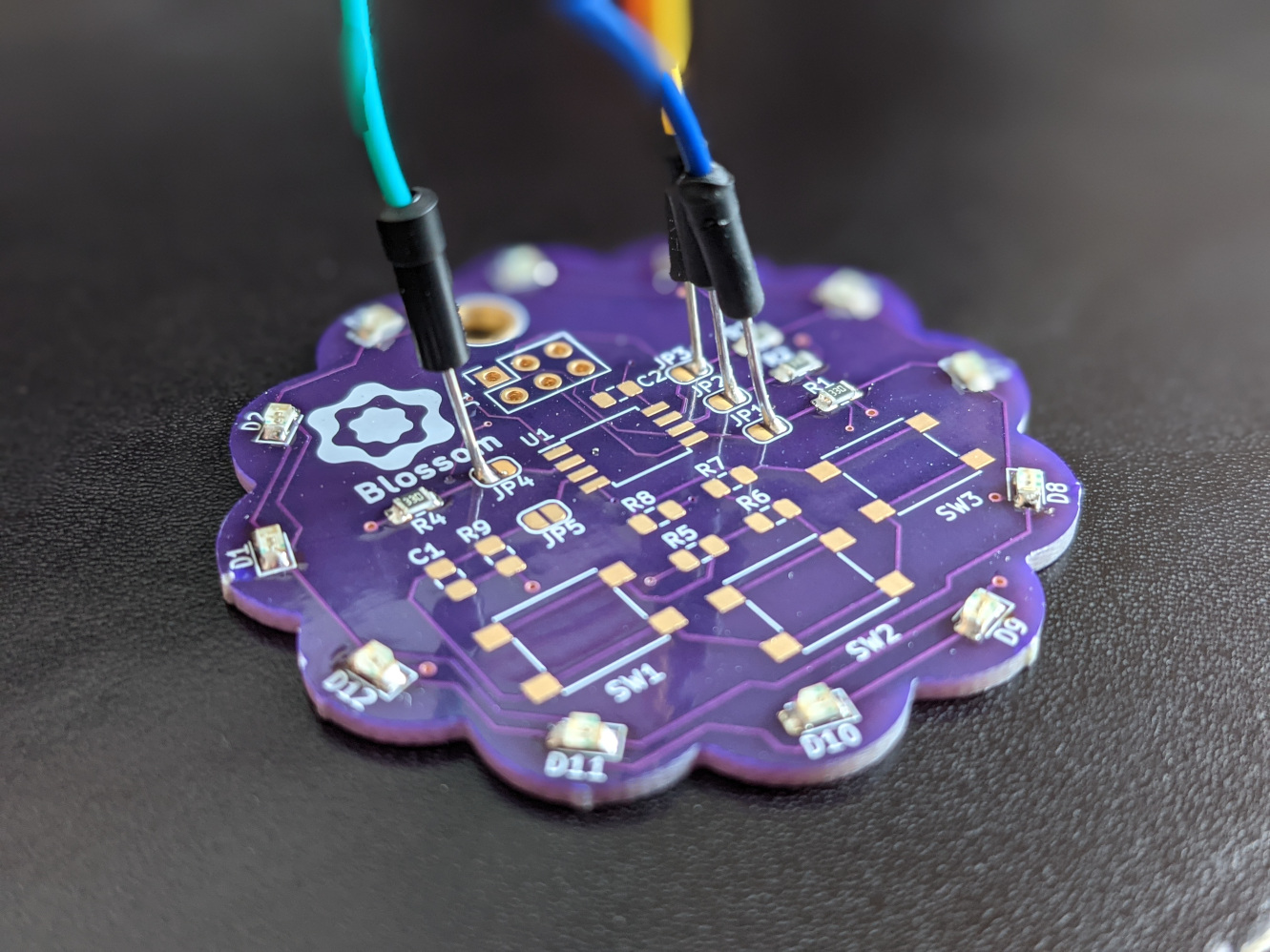
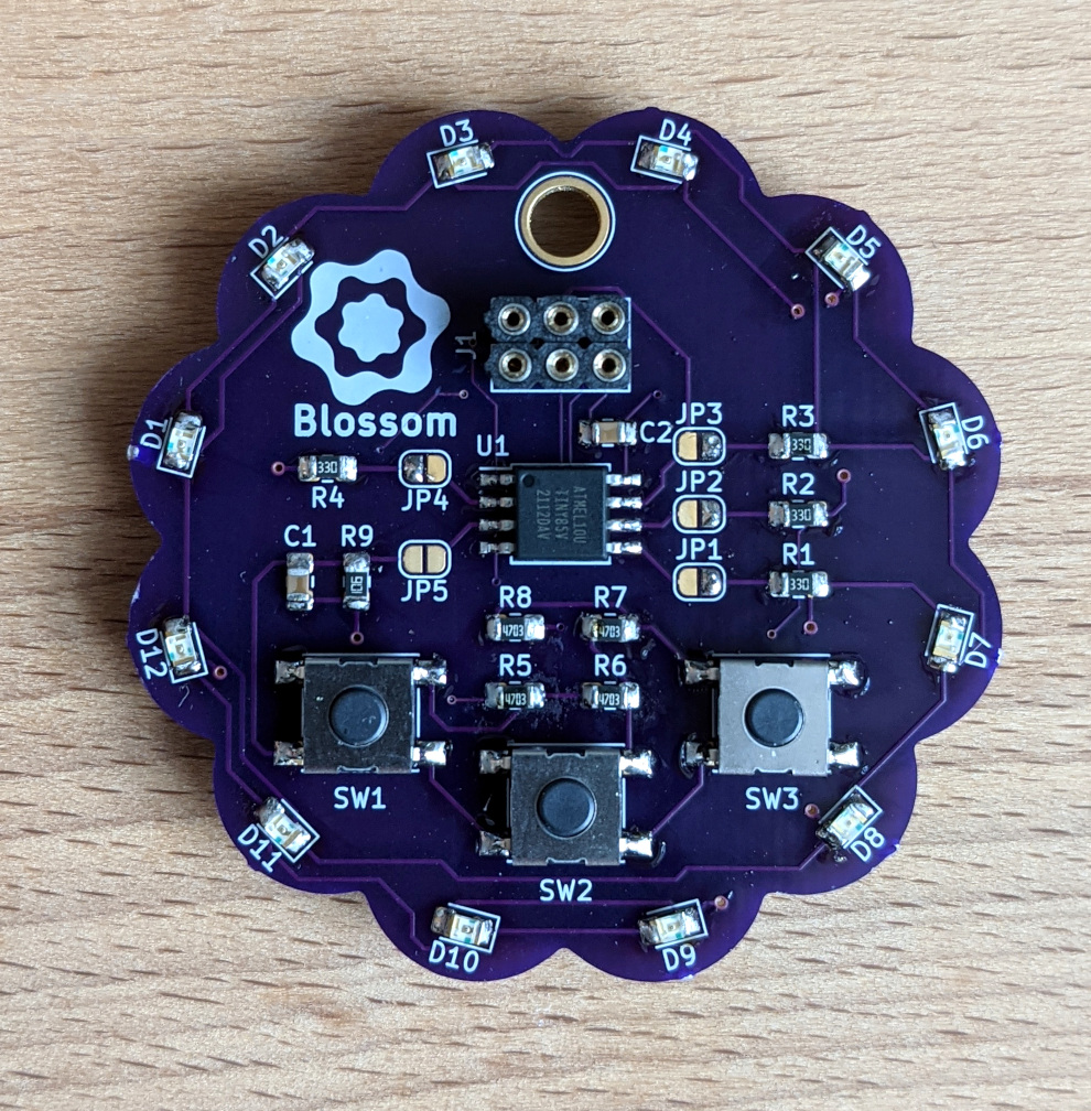
After soldering the remaining components the board looks like this:
Top view (solder bridges were closed)
Bottom view
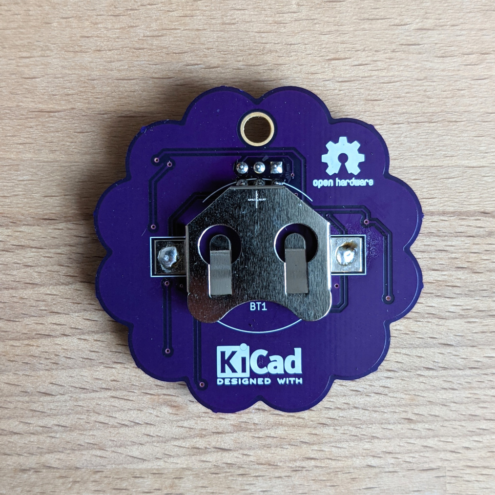
Well, do you see the major problem here? Me neither. And that's where my search began. because I had a short between Vcc and GND...
My Faults
Of course I am also only human and make errors like anyone else. One particularly stupid one will be explained here:
For the battery cell holder I designed my own footprint which is explained in part 1 of this series. Smart as I am I also thought of a adding a courtyard area. Now you may ask yourself: What is a courtyard area? And I would answer something like: Think of it like a safety area, where no other component should be placed. In the case of our battery holder the courtyard is huge and mostly round because of its physical properties.
Okay, so what do we see here?
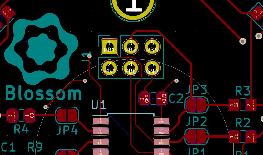
The grey circle is the courtyard of the battery holder. And we can see that in its boundaries is the pinheader. Thats not great, but I managed to not see it because it didn't throw an error. That's because the pinheader has no courtyard defined.
Now after soldering it happened that the three pins on the lower row touched the battery holder... which is of metal... which is conductive...
You want to know which nets are connected to these pins? Vcc and GND. A perfect short circuit. And I still managed to plug it in. facepalm
But eventually I found my mistake and made my second mistake: My solution was to shorten the pins on the side of the battery holder. In order to do that I wanted to remove the battery holder and managed to remove the pads with it...
(insert picture of broken pads here, I don't have one)
Sadly I had to assemble a second PCB, this time with this problem in mind and I was able to complete it.
First Time Uploading
The suspense when uploading a simple program to your new board for the first time is unimaginable. Are all of the connections correct? Is the MCU properly supplied? Is the binary correct?
You have to try it yourself.
For me the outcome was successful at first try. That's the output from avrdude uploading the simple blink example:
Uploading program.hex
avrdude -c usbasp -p attiny85 -P usb -U lfuse:w:0xE2:m -U flash:w:program.hex

avrdude: warning: cannot set sck period. please check for usbasp firmware update.
avrdude: AVR device initialized and ready to accept instructions

Reading | ################################################## | 100% 0.00s

avrdude: Device signature = 0x1e930b (probably t85)
avrdude: NOTE: "flash" memory has been specified, an erase cycle will be performed
         To disable this feature, specify the -D option.
avrdude: erasing chip
avrdude: warning: cannot set sck period. please check for usbasp firmware update.
avrdude: reading input file "0xE2"
avrdude: writing lfuse (1 bytes):

Writing | ################################################## | 100% 0.01s

avrdude: 1 bytes of lfuse written
avrdude: verifying lfuse memory against 0xE2:
avrdude: load data lfuse data from input file 0xE2:
avrdude: input file 0xE2 contains 1 bytes
avrdude: reading on-chip lfuse data:

Reading | ################################################## | 100% 0.00s

avrdude: verifying ...
avrdude: 1 bytes of lfuse verified
avrdude: reading input file "program.hex"
avrdude: input file program.hex auto detected as Intel Hex
avrdude: writing flash (46 bytes):

Writing | ################################################## | 100% 0.04s

avrdude: 46 bytes of flash written
avrdude: verifying flash memory against program.hex:
avrdude: load data flash data from input file program.hex:
avrdude: input file program.hex auto detected as Intel Hex
avrdude: input file program.hex contains 46 bytes
avrdude: reading on-chip flash data:

Reading | ################################################## | 100% 0.03s

avrdude: verifying ...
avrdude: 46 bytes of flash verified

avrdude: safemode: Fuses OK (E:FF, H:DF, L:E2)

avrdude done.  Thank you.
As can be seen the file was uploaded and verified. After that some of the LEDs were happily blinking.
Future Improvements
-
First of all measurement points. They don't cost much space but are very convenient when you want to measure let's say Vcc.
-
Of course the next revision will have pinheader moved out of the courtyard of the battery cell holder.
-
Maybe move C1 to some other place? It is relatively near to SW1 and when touched with your thumb it will charge to a certain level.
That's it for this part. The next blog post will go into the details of programming Blossom.